
Figure 1.
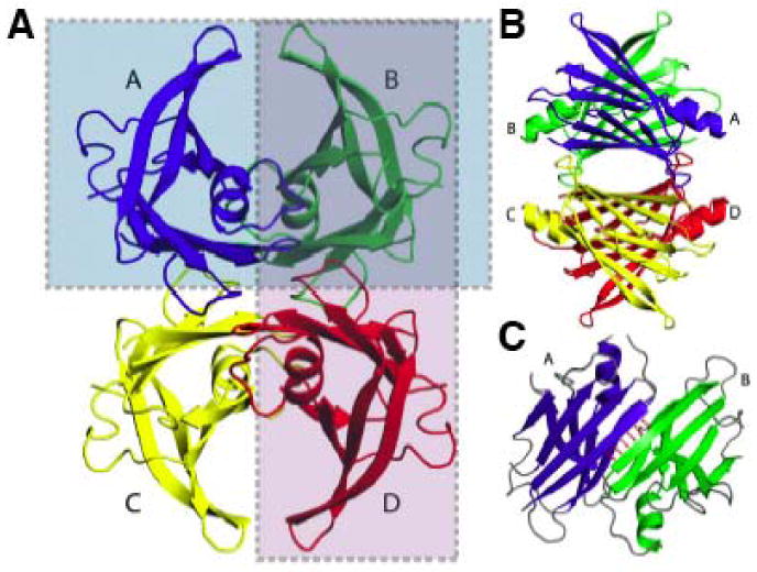
Ribbon diagram depiction of the crystal structure of the TTR tetramer demonstrating the two distinct dimeric interfaces that comprise the tetrameric structure. A) Ribbon diagram of the entire TTR tetramer highlighting the two distinct dimeric interfaces (purple and green boxes). B) A 90° rotation of the image in Figure 1A indicating the dimeric interface that composes the thyroxine binding site of the TTR tetramer (purple box in Figure 1A; comprised of the green and red TTR subunits). C) Crystal structure of the second TTR dimeric interface (green box in Figure 1A; composed of the blue and green subunits). Figure adapted from (43).