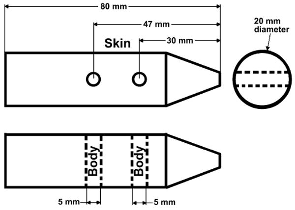
FIG. 1.

Schematic of tissue-equivalent mouse phantom. The top drawing is a side view, and the bottom is a top view (looking down). Thus the two drawings are perpendicular views to each other. The MOSFETs and TLDs were placed on the surface (skin) and interior (body) of the phantom. The phantom was aligned under X-ray guidance to be at the center of the X-ray beam path and with the dosimeters perpendicular to the imaging surface.
