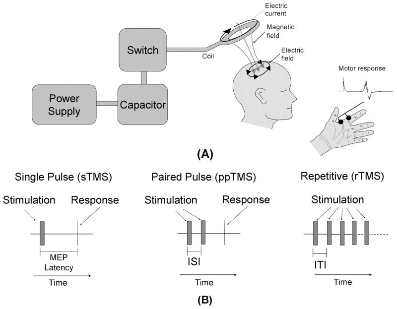
Figure 1.
TMS device and applications. (A) A block diagram depicting the transcranial magnetic stimulator (TMS) circuit is depicted on the left. The power supply charges the capacitor. An operator or computer then signals for the charge stored in the capacitor to be released into the stimulation coil through a thyristor switch. The current flowing through the stimulating coil (here depicted as a circular coil) produces a perpendicular magnetic field which transverses the skull and induces electrical currents within the cortex underlying the coil. A detectable muscle contraction, typically in a contralateral limb, results if the stimulation coil is placed over the motor cortex. This motor response is quantitatively measured as the motor evoked potential (MEP). (B) Three diagrams depicting various TMS protocols. Single-pulse TMS (sTMS) provides a single stimulation to the cortex. If the coil is positioned over the motor cortex, a motor response is elicited. Paired-pulse TMS (ppTMS) stimulates the motor cortex with 2 pulses separated by a short interstimulus interval (ISI). The resulting motor response is compared to the motor response elicited by signal-pulse TMS. Repetitive TMS (rTMS) uses a train of pulses separated by a regular intertrain interval (ITI) for a specific period of time. The duration of the intertrain interval determines the stimulation frequency.

