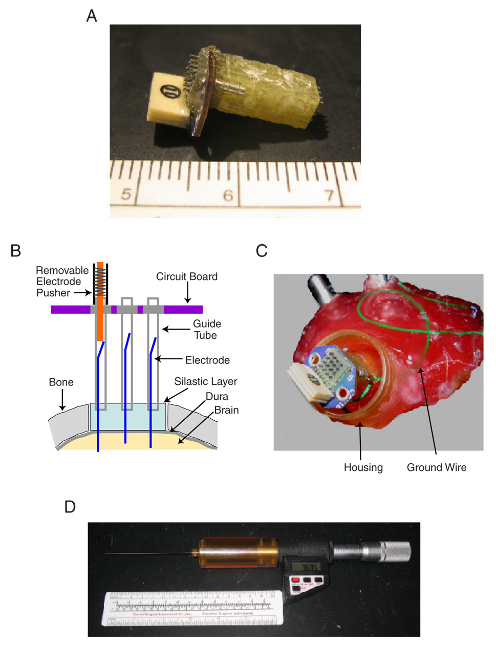
Fig. 1. The Warp16 implanted electrode array.
A: a picture of the electrode array viewed from the side. The maximum dimensions of the array were 17×12×8 mm and its weight is ~0.8 g prior to implantation. B: an illustration of the array design. The array consists of a 4×4 matrix of 15 mm long stainless steel guide tubes (30-gauge) encased in a fiberglass/epoxy matrix and attached to a circuit board. Electrodes are placed in each guide tube and held in place by a ~30° bend in the tail. The bent tail segment lacks insulation and forms the electrical contact between the electrode and the guide tube. A silastic layer fills the space between the array and the dura and serves to both stabilize the electrodes and prevent CSF from leaking back into the guide tubes. C: photograph of the array in-situ. The array is incorporated into the dental acrylic head cap (pink) atop an animal’s skull. A protective housing encases the array and is independently attached to the head cap. When the array was not in use, a small cap was attached to the housing to cover and protect the array. Also visible is a ground wire (green) connecting the array to a skull-anchored grounding screw. D: photograph of the pushing device, modified from a fine caliper, capable of moving electrodes with a resolution of 1 µm. The end of the pusher is a small gauge hollow tube that is lowered until it surrounds the end of a single electrode guide-tube (illustrated in B). A probe wire is then advanced into the guide tube until it makes contact with the tail end of an electrode and then forces the electrode deeper into the brain. Electrode movement is uni-directionally downward; no retraction is possible.

