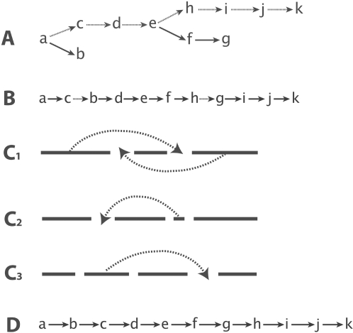
Figure 2. An illustration of the MST-based algorithm.
(A) The MST obtained for a synthetic example; the MST is not a TSP yet; the backbone of the MST is shown with dotted edges. (B) An initial TSP obtained from the backbone (see text for details). The dotted edges represent marker pairs in the wrong order. Several local improvement operations are applied to further improve the TSP, namely 2-OPT (C1), node-relocation (C2) and block-optimize (C3). The final TSP is shown in (D).

