
Fig. 4.
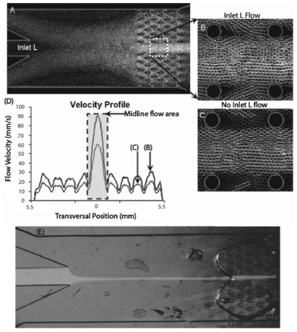
Modeling of the perfusion chamber design was done using Gambit and Fluent (A-C). A plot of the fluid flow velocities (D) during inlet L fluid flow at 10 mm s-1 (B) and 0 mm s-1 (A, C), revealed that removing microposts from the midline achieves more spatial control down the midline of the brain slice (shaded region of D) than through the micropost area. The velocity magnitude is proportional to the gray-scale intensity of the flow vectors. Demonstration of a focused flow of Na+-free solution dye, pumped through the middle inlet by a syringe pump, goes through the midline of the PDMS chamber and brain slice area without any interference from microposts, while clear fluid is pumped through the two side inlets (E).