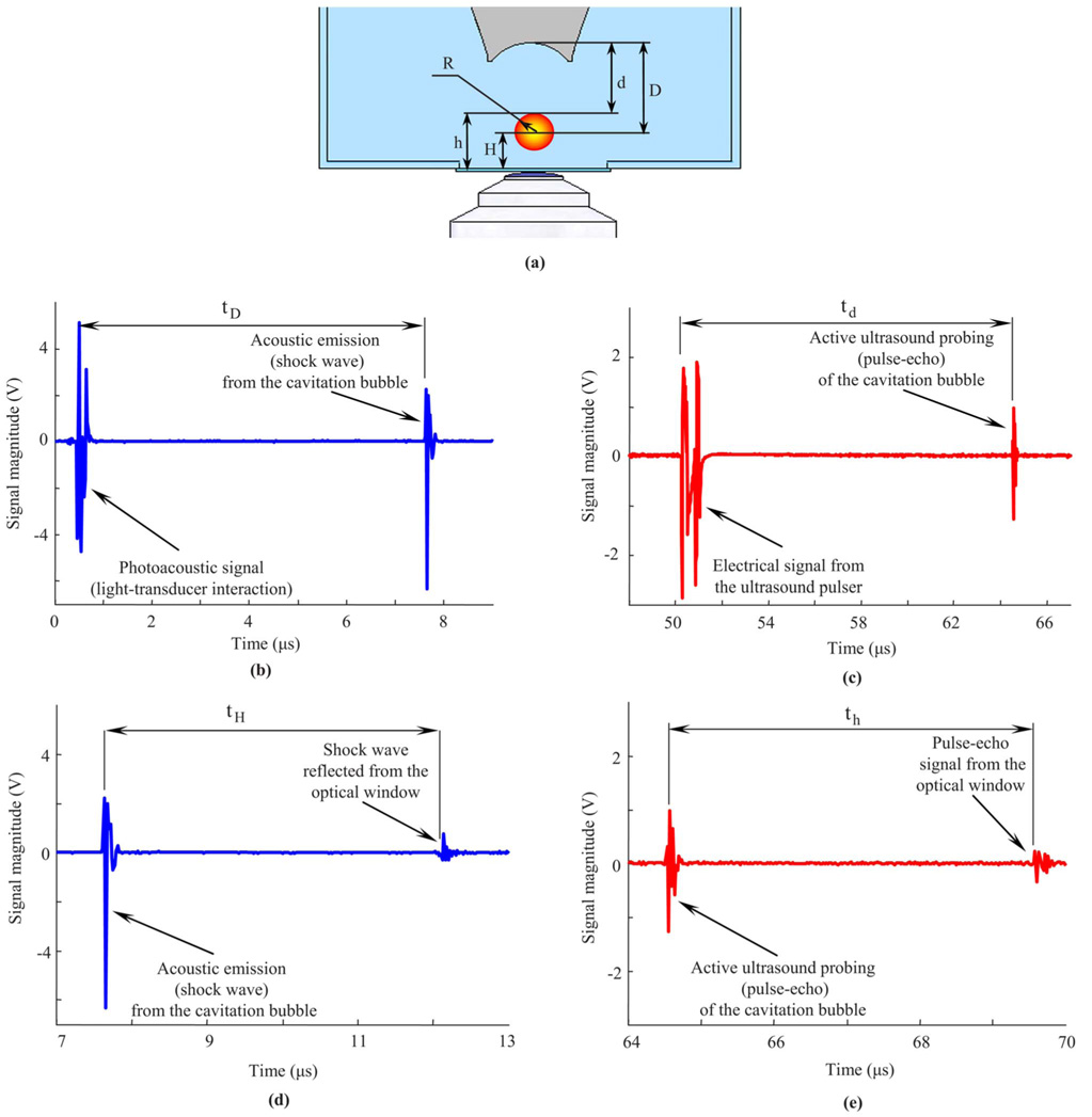
Fig. 3.
(a) Schematic view of the laser-induced cavitation bubble and definition of parameters describing its size and location. (b) Arrival time of the acoustic (shock wave) emission from the cavitation bubble and (c) the time of flight of the pulse-echo ultrasound can be used to determine the origin and size of the bubble. In these measurements, the laser and the ultrasound pulses are used as reference points, so the estimations are relative to the transducer. However, any stationary object such as an internal boundary (optical window at the bottom) also can be used as a reference point. In this case, the instantaneous radius of the bubble can be determined based on both (d) time delay between shock wave emitted from the cavitation bubble and the reflection of the shock wave from the optical window and (e) time delay between pulse-echo signals from bubble surface and the optical window.

