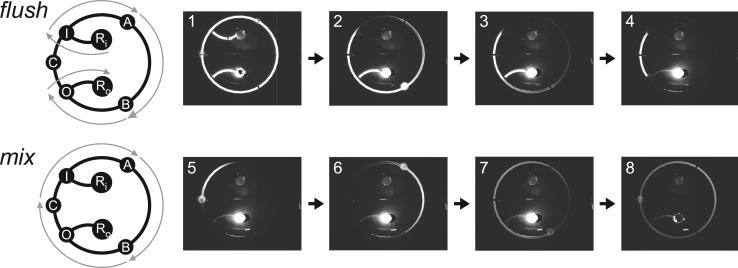
Figure 2.
Serial dilution circuit pumping program schematics and epifluorescence stills. Still frames are 50-ms exposures. The circuit is initially primed with fluorescein dye. Fluid flow paths are indicated with gray arrows overlaid on the circuit schematic. The flush program is used for diluent flushing and carryover isolation, and is accomplished by serially actuating I, A, B, and O while keeping C closed. Buffer is pumped from Ri to Ro, clearing the right side of the mixing loop while isolating the carryover aliquot on the left side (frames 1−4). An example of an open valve can be seen in frame 2, in which B is open and the entire valve is filled with the concentrated dye solution. The mix program is used to mix the diluent and the isolated carryover by serially actuating A, B, and C while I and O are kept closed (frames 5−8). The output reservoir, RO, was manually evacuated in the time between frame 7 and frame 8 for the purpose of visualizing the fully mixed sample. Full movies are included in the Supporting Information.

