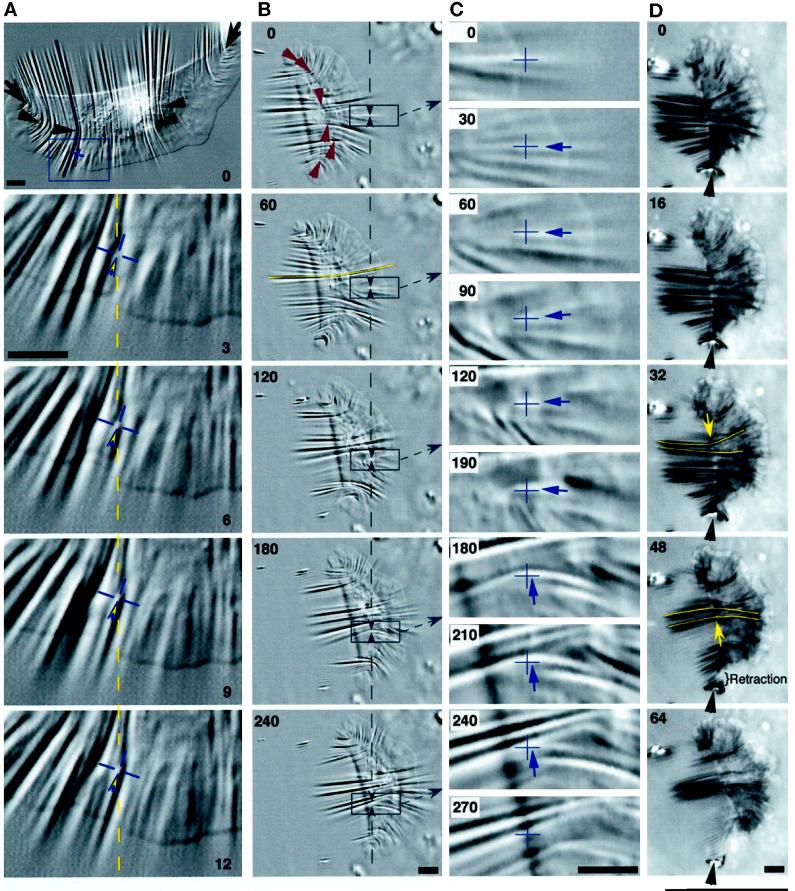
Figure 5.
Traction forces are applied across the entire cell. (A) A large keratocyte that generated high forces on a stiff substratum (wrinkle traced at cell’s right corresponds to 680 nN). Wrinkles were produced at the flanks (arrows) and across the entire cell body (arrowheads). Most wrinkles were located along the boundary of the lamellipodium and the cell body, and the pattern was symmetrical about the midline of the cell. The box at 0 s is magnified in the lower four panels (3–12 s). The cross hair marks the position of the origin of a tension wrinkle, with the direction of force indicated by the arrowhead. The dashed line and the cross hair are at the same position in the field of view in each image, showing very little displacement of the origin of the wrinkle. Numbers indicate seconds. Bars, 5 μm. (B–D) A cell observed in DIC (B and C) and IRM (D). (B) Single arrowheads at 0 s indicate the location and orientation of traction forces producing curved compression wrinkles. The traced wrinkle at the left side of the midline at 60 s corresponds to 600 nN, whereas the force at the right flank was 70 nN. Boxed areas are magnified in C, and intermediate time points are shown. Paired arrowheads in B bracket a constant location in the field of view where a wrinkle was tracked as the cell passed over, shown by cross hairs in C. The arrows in C indicate the direction of force, which rotated by ∼90 degrees as the front of the cell body passed over (see text). (D) Sequence demonstrating the continued presence of central wrinkles when the right flank retracted (arrowheads). The direction of force near the midline reversed as the center of the cell shifted to the left (arrows at 32 and 48 s). Bars, 5 μm.

