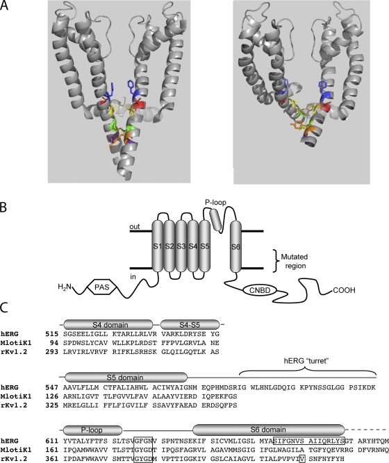
Figure 1.
Topology and alignment of hERG and related channels. (A) Energy-minimized models of hERG in membrane cross section in the closed (left) and open (right) states based on crystal structures of MlotiK1 and rKv1.2 (see text). The S4-S5 linker in shadow and S5 and S6 in gray ribbons from two of the four subunits are shown. S6 residues highlighted are, top-to-bottom: F656 (blue), V659 (red), S660 (yellow; aligns with V478 in Shaker), Q664 (green), Y667 (orange), and S668 (purple). (B) Schematic of one hERG subunit. α-helical transmembrane domains S1 through S6 along with the pore helix are represented as cylinders. S6 domains from each of the four subunits form the ion conduction pathway. The region of mutagenic scan of S6 is bracketed. CNBD, cyclic nucleotide binding domain; PAS, per-arnt-sim domain. (C) Alignment of hERG, MlotiK1, and KcsA used in homology modeling. Selectivity filter and region of mutagenic scan in hERG is boxed, as is rKv1.2 residue analogous to Shaker residue V478, corresponding to the region of the activation gate (Liu et al., 1997; Kitaguchi et al., 2004).

