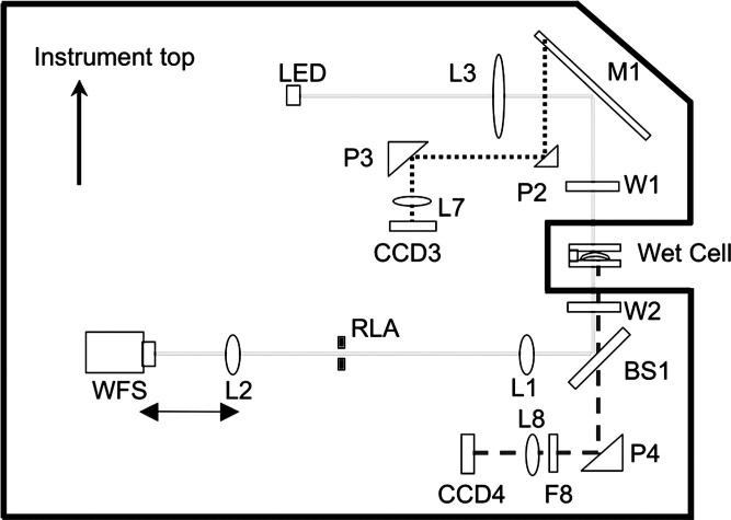
FIGURE 1.
Schematic of ClearWave instrument. The solid outer line represents the instrument casing. The solid line (internal) is the lens measurement path. The dotted line represents the prism camera measurement path. The dashed line represents the alignment camera path of the instrument. (Adapted from figure courtesy of AMO-Wavefront Sciences.)

