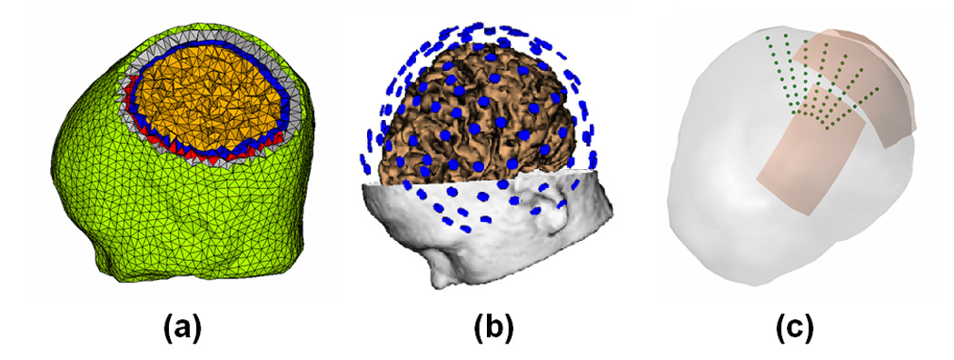
Fig. 1.

The complicated finite element model, EEG electrodes configuration and dipole configurations in the computer simulations. (a) The finite element model consisting of the brain (green), skull (gray), CSF (blue), brain (yellow) and silastic subdural ECoG grid (red); (b) 128 scalp EEG electrodes configuration; (c) 7 dipole groups used in the computer simulations.
