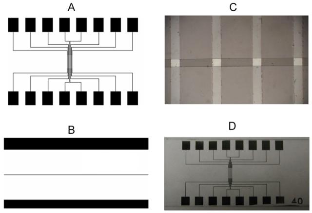
Fig. 1.

The design of the chip device for cell exocytosis measurement using DLC:N microelectrodes. A. Layout of mask for the lift-off process to pattern the electrodes and contact pads, B. Second mask for patterning insulating photoresist that covers the chip except for the contacts pads at the edge and a 30 μm wide line in the middle to define the working electrodes. C. Photomicrograph displaying 4 DLC:N microelectrodes. Vertical lines are the 40 μm-wide DLC:N conducting traces, whereas the horizontal opening of the photoresist defines the 30 μm by 40 μm working electrodes. D. Photograph of completed chip device on a 25 mm by 75 mm glass slide.
