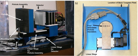
Figure 6.
(a) Close-up of the adaptive imaging system. The object stand can be seen sitting on top of the rotation stage, to the right of that is the pinhole assembly, and slightly further to the right the detector is shown. (b) Picture showing detail of the pinhole assembly. The top tungsten plate has been removed.

