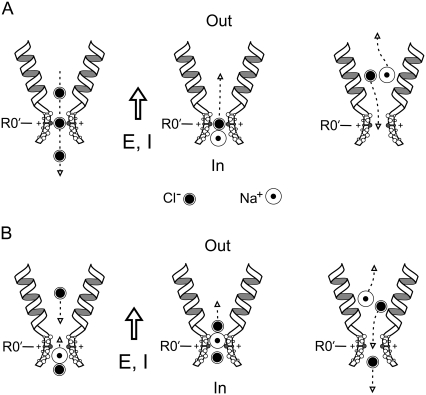
FIGURE 7.
Two possible schematic models (A and B) to explain counterion permeation through the selectivity filter (SF) region of GlyRs. In each case, the channel and equivalent hydrated ions are drawn approximately to scale for the dimensions of the SF region of the P−2′Δ mutant GlyR. As in Fig. 6, the relative protrusion into the channel lumen reflects the electrostatic contribution of the critical selectivity residues and the proposed β-strand structure of this region, rather than meaning to specify the precise orientation of these residues. The open arrows give the direction of the electric field (E) and net current (I). For these schematics, a positive potential (inside–outside) has been chosen such that the electrical gradient dominates the chemical activity gradient, which has been chosen such that it is from inside to outside. The electrical gradient (and electrochemical gradient) hence favors Na+ flux from inside to outside, and Cl− flux from outside to inside (e.g., +30 mV, with an external 0.5 NaCl dilution). The predominant outward current is due to an inward movement of anions (e.g., as shown in the left panel of A). In panel A, it is proposed (as in the middle panel) that periodically an Na+-Cl− ion pair is formed near the internal end of the SF region and that the “neutral” ion pair is able to diffuse through the SF region down its concentration gradient, with the Na+ counterion being effectively chaperoned. If the complex then dissociates once it has passed through the SF region, the Na+ ion should continue to move in the direction of the electric field, as indicated by the dashed arrow in the right panel, and so contribute to the net current flowing through the channel. The dissociated Cl− ion should now move in the opposite direction to the electric field, back through the SF region, and so not contribute to the net current through the channel. Hence, the net result will be one Na+ ion moving through the channel (cf. Fig. 8, A and B, of Keramidas et al. (1)). Our panel B is somewhat similar to the model of Franciolini and Nonner (9) (see their Fig. 10), except that we are assuming that the ions will carry with them most of their hydration shells and we have not specified any detailed interaction with both polar and charged sites lining the SF region. We again assume that periodically an Na+-Cl− ion pair is formed (as shown in the left panel) and is able to diffuse toward the SF region, with the Na+ ion (at least intermittently) aligned toward the SF. As Cl− ions, which will be moving down their electrical gradient from outside to inside (also left panel), approach the SF region, they will make it easier for the Na+ ion to form a neutral ion pair with the Cl− ion. The neutral ion pair can then diffuse away from the SF region, as in the middle panel. As it moves away from the constricted region, it will tend to dissociate and the Na+ ion will now move down its electrical gradient and the Cl− ion is now free to again move toward the SF region (right panel).

