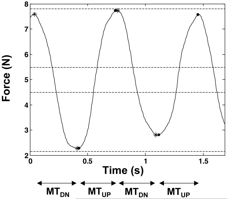
Figure 2.
An example of MT definitions for two MTUP and two MTDN time intervals for a task (actual data is shown). Force output by instructed fingers is shown as a solid line; targets are denoted by bands between two sets of thin dashed lines. The beginning and end of MTUP intervals are denoted by filled-in circles; the beginning and end of MTDN intervals are denoted by asterisks. Both MTUP and MTDN intervals are also denoted by arrows for clarity. Note that both MTUP and MTDN intervals are defined by 5% of the absolute maximum velocity (|vmax|) within a half-cycle of an oscillation.

