
FIG. 6.
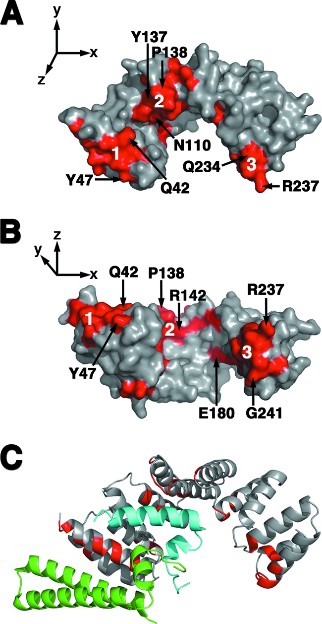
Potential PilF interaction interfaces. (A and B) The three conserved surfaces of PilF are highlighted in red on these surface representations of the PilF molecule. The molecule in panel B is drawn orthogonally to the representation in panel A. Representative residues from each conserved surface are labeled. The N-terminal, central groove, and C-terminal clusters are labeled 1, 2, and 3, respectively. (C) The substrates of PscG were overlaid on the monomer of PilF after alignment of the PscG and PilF TPR motifs. PilF is drawn in the same orientation as in Panel A. Residues that belong to the three conserved clusters on the surface of PilF are shown in red on the ribbon diagram. The substrates PscE and PscF are colored in green and light blue, respectively.