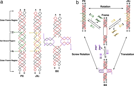
Fig. 1.
Schematic drawings of the three-state device. (a) The PX, JX2, and BX motifs. The Frame consists of two strands, one drawn in red and one in black, where arrowheads indicate the 3′ ends of strands. The outer Frame regions consist of PX-DNA, two double helices wrapped around each other. The green set strands in the PX motif (left) continue this pattern. The toeholds, used to remove the set strands, are drawn as horizontal lines, one on the 5′ end and one on the 3′ end. The set strands in the JX2 motif are drawn in yellow, but the same conventions apply. Note the lack of two crossovers in the set strand region. The set strands in the BX motif are drawn in purple, and the toeholds are vertical. The color-coding of the strands and labels in Fig. 1a indicates that the top ends, A and B, are the same in all of the molecules but that the bottom ends, C and D, are rotated 180° in JX2 and BX molecules. BX is contracted vertically, relative to PX and JX2. (b) Principles of device operation. The three states are shown at the corners of this diagram, and the nature of the transitions (rotation, translation, or screw rotation) is indicated by labels next to the double-headed arrows. All transitions go through the unstructured Frame, shown in the center of the diagram. The addition of set strands (drawn as colored arrows) transforms the Frame to the PX state (green set strands), the JX2 state (yellow set strands), or the BX state (purple set strands). The set strands can be removed from any motif by the addition of the unset or fuel strands, drawn as arrows with black dots (representing 5′ biotin groups), thereby returning the device to the Frame state; the duplex molecules so generated can be removed by the addition of streptavidin-coated magnetic beads.

