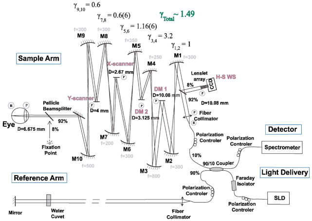
Fig. 1.
(Color online) Schematic of AO-OCT system. “R” and “P” denote retinal and pupil planes, respectively. DM1, bimorph deformable mirror (AOptix); DM2, MEMS DM (Boston Micromachines) are optically conjugated [by sets of the spherical-mirror—(Mn)-based telescopes] with the subject’s eye pupil, X–Y scanners and the H-S wavefront sensor. The reference arm of the AO-OCT system is designed to match the path length of the sample arm. A fixation point is used to set the retinal location of the imaged structure.

