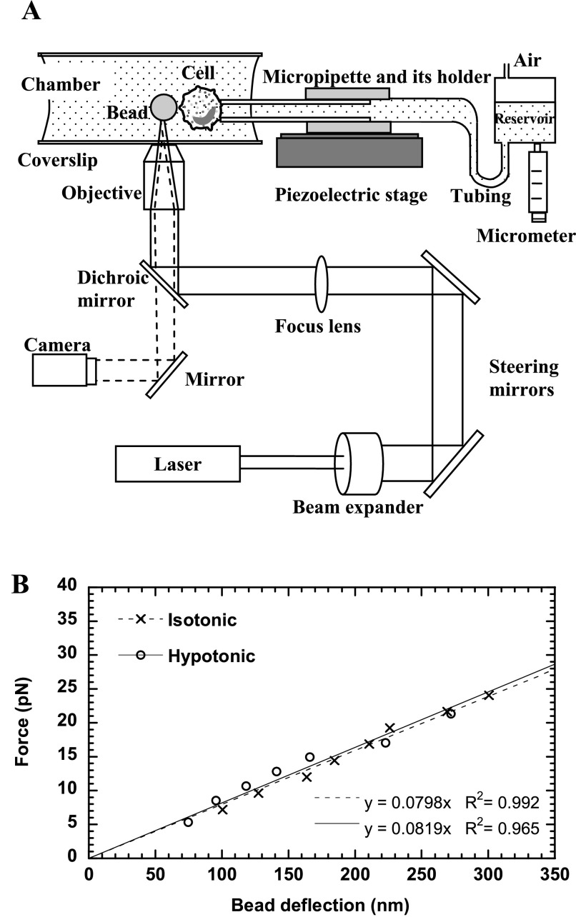
Fig. 1.
The optical trap (OT) setup and calibration. A: schematic of the OT setup combined with a micropipette manipulation system (not drawn to scale). Solid lines represent the laser beam path, and dashed lines represent the imaging light path. The laser was expanded and directed into the back aperture of the objective of the microscope. The laser focused by the objective can trap a latex bead and function as a soft mechanical spring, whereas the micropipette can hold a cell with suction pressure applied by adjusting the height of the reservoir. The motion of the piezoelectric stage where the micropipette is affixed is controlled by a computer. B: calibration of the OT stiffness in isotonic or hypotonic media. The slope of the fitted lines gave the trap stiffness of ∼0.08 pN/nm.

