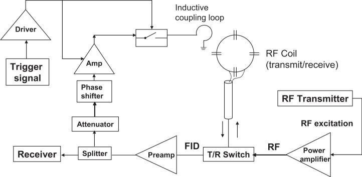
FIG. 1.
Schematic diagram of a feedback device for enhancing the radiation damping (RD) field in an MR scanner. The received MR signal was split following amplification by the preamplifier, with a portion of the acquired signal continuing to the receiver and the remaining signal being diverted to the feedback device. The MR signal entering the feedback device was then attenuated, and the attenuated signal served as the input of a phase shifter. The signal was amplified via a low-noise amplifier and applied to the input of a switch. The amplifier and switch were powered by a driver, which was in turn triggered by the pulse sequence (Fig. 2). The feedback field was inductively coupled to the sample through a small wire loop.

