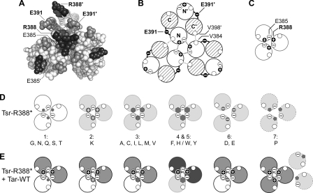
FIG. 6.
Structural features of the tip region in receptor trimers of dimers. (A) End-on view of the trimer in Fig. 1B showing the cytoplasmic tip and the relative positions of R388 (black), E391 (gray), and E385 (dark-gray) residues in the trimer of dimers. (Symmetry-related residues in the trimer are not explicitly labeled.) Note that the two E391 residues in a dimer occupy roughly equivalent positions in the trimer, whereas the E385 and R388 residues do not. At the trimer interface, R388 forms a salt bridge with E385 in the adjacent dimer, which serves to stabilize the trimer arrangement. The corresponding residues (R388′ and E385′) in the nonaxial subunits of the trimer do not engage in interactions between dimers. (B) Schematic of a trimer containing three Tsr-WT (wild-type) dimers. Helices at the N-terminal side of the tip are shown as open, and those at the C-terminal side of the tip are shown with cross-hatching. The E391 residues lie in the loops connecting the N- and C-terminal helices of each subunit. In the trimer, each dimer contributes residue contacts from two helices (N and C′) to the trimer interface, with the majority of interactions, including those between R388 and E385 shown here (thick dashed lines), involving residues in the N-terminal helices. A few additional trimer contacts involve interactions (thin dotted lines) between residues in the N and C′ helices, for example, V384 (N) and V398′ (C′). (C) Schematics of the major (N-terminal) trimer contact helices in trimers of dimers from Fig. 7B showing the R388 and E385 interactions. The unfilled circles represent V384. (D) Schematics of the major (N-terminal) trimer contact helices in Tsr-R388* mutant trimers of dimers. The white helices depict mutants with residual Tsr function, and the light-gray helices depict mutants with no Tsr function. The small dark-gray symbols depict the mutant amino acid replacements. All mutants except R388D, R388E, and R388P probably make trimers with reduced stability (group 1, G, N, Q, S, T; group 2, K; group 3, (A, C, I, L, M, V) or altered geometry (group 4, F, H; group 5, W, Y). The D, E (group 6) replacements introduce acidic residues that probably prevent stable trimer formation through charge repulsion with E385. The P (group 7) replacement probably destabilizes the N helices, disrupting the major trimer contact interface (dashed outline). (E) Schematics as in panel D showing the probable composition and function of mixed trimers of dimers in R388* jamming and rescue tests with Tar-WT. Tsr* helices, functional, white, and nonfunctional, light gray; Tar helices, functional, gray, and nonfunctional, dark gray. Mixed trimers containing a group 1, 2, 3, or 6 Tsr* dimer exhibit both Tar and Tsr functions because they have most of the correct residue contacts at the trimer interface. However, mixed trimers containing group 4 or 5 Tsr* subunits (F, H/W, Y) have neither Tsr nor Tar function, perhaps owing to an altered trimer geometry or dynamic behavior caused by the Tsr* member. The R388P receptor (group 7), which is neither rescuable nor jamming, probably fails to form stable mixed trimers with Tar.

