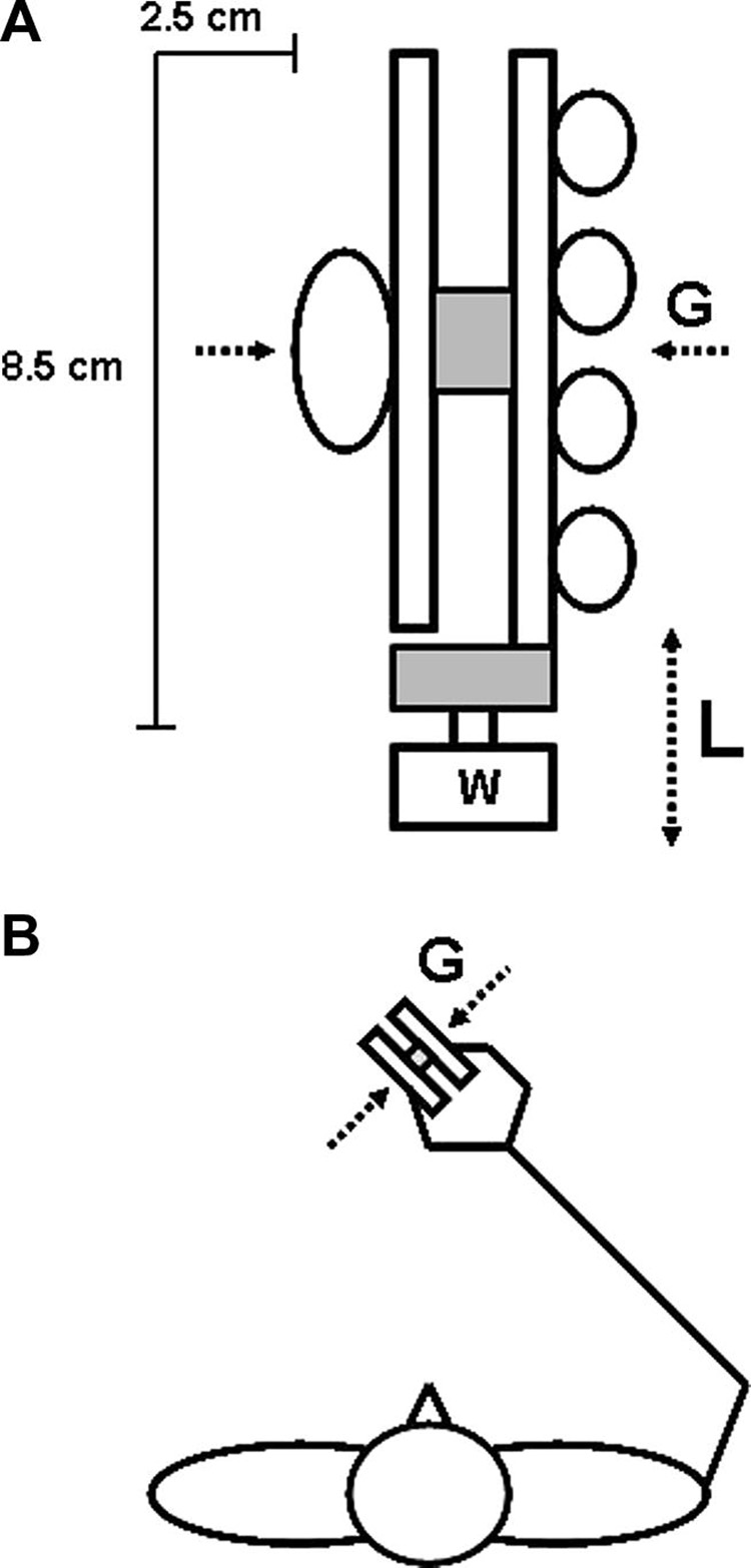
Fig. 1.
(A) Schematic illustration of the device (not drawn to scale). The circles illustrate the position of the tips of the fingers and the thumb applying a precision grip against the handle. W indicates external load that could be attached to vary the total weight or, alternatively, fixation of the device to the table. The upper and lower shaded rectangles depict the force sensor that record grip force (G; perpendicular to device) and load force (L), respectively, applied against the device. (B) The stick diagram illustrates the horizontal projection of the subjects' body position while performing the tasks.

