Abstract
We have developed a portable high power ultrasound system with a very low output impedance amplifier circuit (less than 0.3 Ω) that can transfer more than 90% of the energy from a battery supply to the ultrasound transducer. The system can deliver therapeutic acoustical energy waves at lower voltages than those in conventional ultrasound systems because energy losses owing to a mismatched impedance are eliminated. The system can produce acoustic power outputs over the therapeutic range (greater then 50 W) from a PZT-4, 1.54 MHz, and 0.75 in diameter piezoelectric ceramic. It is lightweight, portable, and powered by a rechargeable battery. The portable therapeutic ultrasound unit has the potential to replace “plug-in” medical systems and rf amplifiers used in research. The system is capable of field service on its internal battery, making it especially useful for military, ambulatory, and remote medical applications.
INTRODUCTION
In the past two decades, researchers and clinicians have shown that therapeutic ultrasound can be an effective tool in relieving arthritis, improving rehabilitation, and enhancing wound healing.1, 2, 3, 4 Ultrasound at higher energy has proven useful in surgical applications such as prostate therapy and brain tumor and cardiac tissue ablation.4, 5, 6, 7 Ultrasound may also be useful in improving a variety of drug delivery platforms, including large-molecule transdermal delivery, targeted chemotherapy for brain cancer, and cellular gene transfer.8, 9, 10, 11 In addition, the combination of ultrasound-based imaging with ultrasound-based therapy has potential for important military and medical applications.12, 13, 14 Despite the widespread use of ultrasound, the basic idea in producing ultrasound power has not changed significantly in the past 50 years.6, 13, 15 Established methods for ultrasound driving systems, such as high voltage switching and rf amplifiers, often require bulky and expensive equipment. Thus, the development of a cost-effective, portable system for delivering ultrasound could greatly enhance the use of ultrasound across a broad range of medical therapies.
In the late 1920s initial studies of the biological effects of ultrasound were performed by Wood and Loomis.16 Since then, researchers have proposed systems to produce high power ultrasound. In 1942 Lynn et al.17 introduced an effective 836 kHz high voltage (3000–6000 V) low current (900 mA) ultrasound driver for biological research, which was based on vacuum tube technology and radio transmitter design. Since in-house power and very high voltages were used in this design, precautions were taken to avoid electrical shock and rf interference. Lynn’s system and power outputs were measured crudely by measuring the rise of a conical oil cone from the radiation force exerted by the focused ultrasound energy. Fry et al.18 in 1986 presented a focused ultrasound system for tissue volume ablation of brain tumors. The power of the system was supplied by a 990 kHz tuned (impedance matched) 2 kW amplifier with preamplifying circuitry. Lee et al.19 in 1999 introduced a 64-channel rf driving unit with phase control to produce local hyperthermia in vitro and in vivo. The amplifier stage of the system used transistor-transistor-logic (TTL) timing with an unspecified in-house built circuit to amplify the drive signal. The 8.0 MHz array Lee et al. developed produced acoustic powers from 0–1 W. Owen et al.15 in 2003 developed a 12 lb plug-in class D switch-mode amplifier to drive single element high intensity focused ultrasound (HIFU) transducers. The system provided 140 W of acoustic energy from a 70% efficient lead zirconate titanate (PZT) transducer with 33 mm diameter and 55 mm radius of curvature. Owen et al.15 compared the device with products on the market at the time and found their device favorable because of its light weight and ability to cause hemostasis and tissue necrosis.
Commercially available ultrasound drivers and rf amplifiers are generally built with a 50 Ω output impedance that has high voltage amplification and switching of the applied ac signal. To date, many of the developed ultrasound drivers have been impedance matched to enhance power transfer as stated in the maximum power-transfer theorem: to obtain maximum external power from a source with a finite internal impedance, the impedance of the load must be made the same as that of the source. The 50 Ω output impedance is matched to the transducer using special impedance-matching circuitry to maximize power transfer and minimize reflections from the ultrasound transducer.6, 13, 15 From voltage division, the voltage across the transducer is inversely related to the impedance of the source. Therefore, if the source has a 50 Ω output impedance and the transducer has a 10 Ω purely resistive impedance, only 17% of the energy from the source will be supplied to the transducer. The rest will be reflected or lost as heat. When impedance-matching circuitry is used, one-half of the power from the source is transferred, and the driver becomes more efficient. In matching the characteristic impedance of the driver to the ultrasound probe, which generally has complex impedance, automatic tuning devices are used that add to the cost and bulk of the system.15
We have developed a plug-free portable high power ultrasound system with a very low output impedance amplifier circuit (less than 0.3 Ω) that is capable of transferring more than 95% of the voltage from the battery supply to the transducer. Because the output impedance of the drive circuitry and metal-oxide-semiconductor field-effect transistor (MOSFET) switching loss is negligible compared with the ultrasound transducer’s impedance, little energy is lost as heat. Furthermore, because the batteries can provide high current, much lower voltages are required to create therapeutic acoustical energy waves than in conventional systems. The system can produce acoustic power outputs over the therapeutic range (greater than 50 W). It is lightweight (under 6 lb), portable (2×6×4 in.3) and powered by a rechargeable battery, which makes it suitable for a variety of military, ambulatory, and field medical applications.
METHODS
The portable therapeutic ultrasound system comprises the low impedance ultrasound driver, accompanying circuitry, and the ultrasound transducer probe. This section describes each part of the apparatus and measurements to determine the power of the device, acoustical driving efficiency, portability, and robustness.
Driving circuit
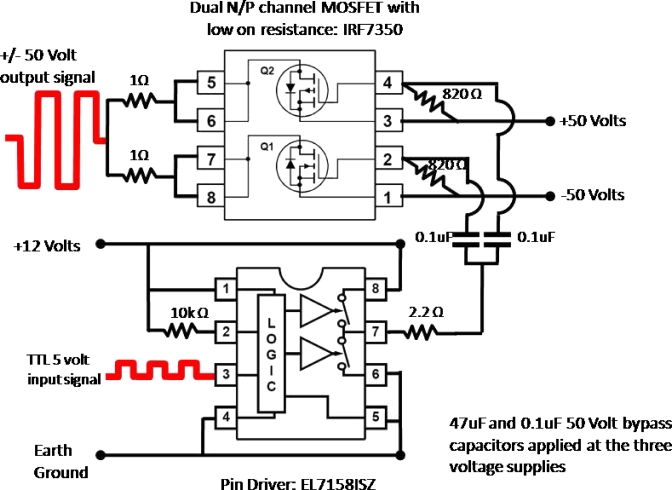
The circuit for the low-output-impedance driver is shown in Fig. 1. A pin driver (EL71581SZ, Intersil, Inc.) that is capable of driving high capacitive loads is supplied with a 5 V square wave TTL input at pin 3. The input timing signal comes from a 1.54 MHz crystal oscillator (SE1216-ND, Epson Toyocom, Inc.) that fits the ultrasound probe’s resonant frequency for maximum power transfer. Pins 1 and 8 are held at +12 V with 47 and 0.1 μF bypass capacitors to ground. Pin 2 is connected to pin 1 with a 10 kΩ resistor. Pins 4 through 6 are connected to earth ground. Pin 7 of the pin driver is the output that provides a 12 V square wave to regulate the switching of the metal-organic-semiconductor field-effect transistors (MOSFETs) voltage drain. From pin 7 of the pin driver a 2.2 Ω resistor splits off with two 0.1 μF coupling capacitors into the input pins 2 and 4 of the low on resistance N∕P channel MOSFET (IRF7350, International Rectifier, Inc.). Pins 1 and 3 of the MOSFET are held at a maximum of −50 and +50 V, respectively, with 820 Ω resistors across pins 1–2 and 3–4. A 47 μF and a 0.1 μF bypass capacitors to ground are applied as well to pins 1 and 3 of the MOSFET. Pins 5–6 and 7–8 of the MOSFET are tied together and coupled through 1 Ω, 5 W power resistors with the output drive signal applied to the ultrasound transducer through a standard BNC connector.
Figure 1.
Circuit schematic of the low output impedance ultrasound driver. A pin driver is appropriately timed with a TTL 5 V signal from a 1.54 MHz crystal oscillator that switches the drain of the low output impedance MOSFET from ±50 V maximum.
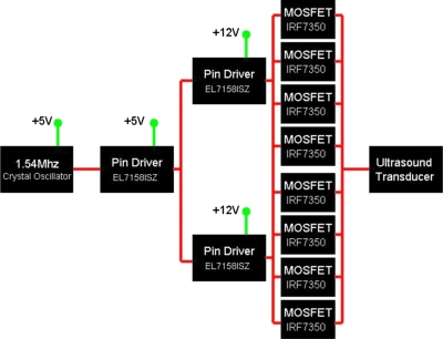
The Intersil, Inc. EL7158ISZ pin driver acts as the logic switch for the MOSFETs that supply the power oscillation drive to the ultrasound transducer. For high power continuous wave applications requiring high current, pin drivers are used to switch MOSFETs in parallel to lower the current burden on each MOSFET. As shown in Fig. 2, a single timed pin driver at 5 V drives two pin drivers at 12 V as a branching cascade to switch four MOSFETs each for the portable high power ultrasound driving system. Each pin driver∕MOSFET unit is wired as shown in Fig. 1. The output impedance of the driver was measured directly, and determined from manufacturer values of the MOSFETs, and eight 1 Ω parallel resistors to be almost entirely resistive and approximately 0.2–0.3 Ω.
Figure 2.
Driving circuit used in portable ultrasound system. The working unit of Fig. 1 may be applied in parallel stages to reduce the power/heat dissipation in each MOSFET to allow for high current driving to the transducer.
System design
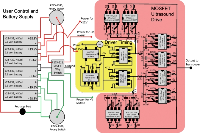
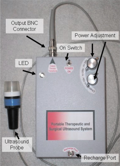
Figure 3 shows a schematic of the complete system, and Fig. 4 is a photograph of the finished device. Figure 3 is divided into the battery supply and user control portion (left), TTL logic timing signal (middle yellow box), and parallel MOSFET ultrasound driving stage (right red box). The system is housed in a 4×6×2 in.3 watertight plastic enclosure (No. 073, Serpac, Inc.). The housing holds the circuit (1.5×2×1 in.3) and six 9.6 V, 1600 mA h NiCad rechargeable battery packs (No. 23–432, Radio Shack, Inc.) tied together in series through two single draw rotary switches. The user can adjust power delivery to the transducer through the MOSFETs in 9.6 V increments over the range ±28.8 V. A blue “on” light-emitting diode (LED) is tied into the on∕off switch that supplies power to the crystal oscillator and pin driver through 5 and 12 V 1 A voltage regulators that also have bypass capacitors. The output of the device is terminated in a male Bayonet Neill Concelman (BNC) connector on the front panel. A battery recharge port at the back of the system is wired to charge the six battery packs in series. To charge the system, the device is switched to the off position and the rotary switches are moved to a nonconnected terminal as labeled on the devices panel.
Figure 3.
Wire layout for portable ultrasound system.
Figure 4.
Portable therapeutic ultrasound system with 1.54 MHz ultrasonic probe. The unit is 4×6×2 in.3 and weighs 5.5 lbs.
Ultrasonic probe
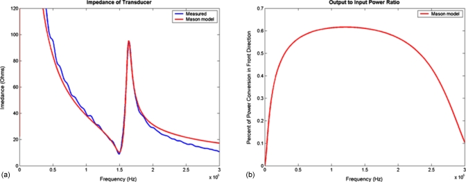
The ultrasound probe is constructed from PZT-4, 1.54 MHz, and 0.75 in diameter piezoelectric ceramic with a radius of curvature of 1.5 in (EBL Products, Inc.). The ceramic (air-backed) is housed in a polyvinyl chloride (PVC) ergonomic plastic assembly that was built in-house on a microlathe and milling system (Sherline Products, Inc.). The clear acrylic front of the transducer acts as a protective cover to the ceramic and an in-plane focal alignment standoff for the ultrasound energy. The probe is wired with 22 gauge coaxial cable terminated with a female BNC connector. The electrical impedance of the ultrasound probe was measured using commonly known methods (Fig. 5), to determine the resonant frequency for high power driving efficiency.20
Figure 5.
(a) Measured impedance and results from a Mason model of transmission lines. (b) Calculated acoustic conversion efficiency from the Mason model.
Measurements and characterization
The output waveform and power spectrum of the device were collected using a Tektronics model TDS2002B oscilloscope with the ultrasound probe attached and placed in an acoustically insulated water bath. The output impedance, resistance, and reactance of the device were measured by attaching a 12 Ω power resistor across the output of the device and measuring the phase and voltage changes across the component. The ultrasonic power output was determined with a force balance technique in which we measured the force that the ultrasound exerted on an acoustic absorbing object.21 We compared these results with electrical measurements of power using the electrical properties of the probe and a measured ultrasonic power conversion efficiency.22 Battery life was determined for various output powers. The device was tested with other ultrasonic probes by interchanging the 1.54 MHz crystal oscillator with a function generator. The system was run with 1.7, 2.2, and 7.5 MHz transducers, and the output wave form was measured.
RESULTS
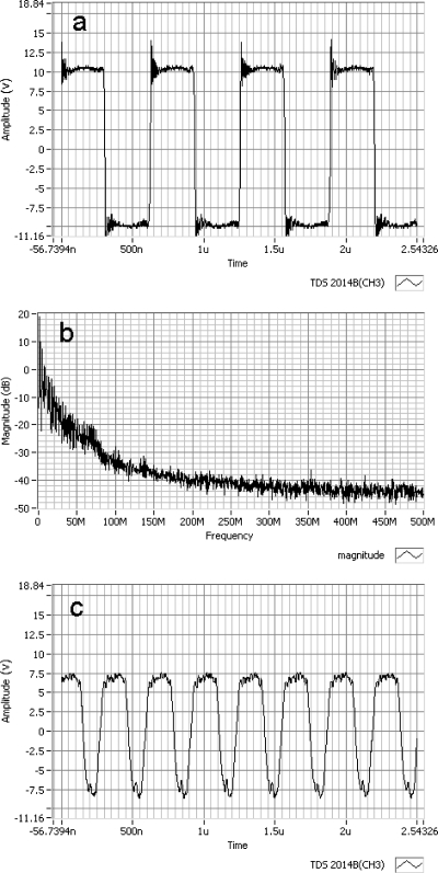
The waveform of the device output and power spectrum at the 19.2 Vpp-Vpp battery setting are shown in Figs. 6a, 6b. Figure 6c is the measured output waveform from the device while connected to a function generator driving a 7.5 MHz probe under equivalent power application. Slight ringing at the corners of the 1.54 MHz waveform is shown in Fig. 6a; however, the driving signal is reasonably clean with no oscillations in the waveform and fast rise times between the push-pull cycles. The power spectrum, shown in Fig. 6b, of the signal in Fig. 6a is representative of a typical square-wave drive signal with corner signal spikes. Figure 6b shows the drive signals; energy concentration is in the early megahertz frequencies. Figure 6c shows that the amplitude of the driver is attenuated for the higher frequency of 7.5 MHz. Furthermore, the waveform is asymmetric and exhibits small oscillations for positive and negative sides. When the TTL timing frequency is increased into the 10 MHz range, the MOSFETs saturate and are unable to switch∕operate at these speeds. The output resistance and reactance of the device was measured to be less than 0.3 Ω and almost entirely real with no measurable phase shift.
Figure 6.
(a) Measured 1.54 MHz output waveform from the device with slight ringing at the corners. The driving signal is mostly clean with no oscillations in the waveform and fast rise times between the push-pull cycles. (b) The power spectrum of the 1.54 MHz waveform. The drive signals energy concentration is in the early megahertz frequencies. (c) Measured while the timing signal came from a function generator, the higher frequency of 7.5 MHz lead to attenuated drive voltage and asymmetry of the waveform with oscillations on both the positive and negative sides.
The electrical impedance for the ultrasound transducer probe of 12 Ω and an acoustic conversion efficiency of 63% at 1.54 MHz were obtained from the data shown in Fig. 5, and used to determine power from the voltage measurement across the transducer. The ultrasonic power was measured at each power setting and results are shown in Table 1. The force balance approach gave slightly higher acoustic power values compared with the electrical power measurements. Acoustic output powers ranged from 5.77 to 51.4 W, with a maximum difference of 23% between the two power measurement methods.
Table 1.
Acoustic power measurements and battery life.
| Voltage settingVpp-Vpp (V) | Force balance (W) | Electrical measurement (W) | Power average (W) | System battery life (h) |
|---|---|---|---|---|
| 19.2 | 6.28 | 5.25 | 5.77 | 1.7 |
| 28.8 | 10.5 | 11.8 | 11.5 | 1.2 |
| 38.4 | 23.5 | 21.0 | 22.5 | 1.0 |
| 48.0 | 43.4 | 32.8 | 38.1 | 0.8 |
| 57.6 | 55.8 | 47.3 | 51.4 | 0.7 |
The battery life at each power setting for sustained power output after full charge is also tabulated in Table 1. Maximum system life was for 1.7 h at 5 to 6 W of acoustic energy. At the maximum acoustic energy setting, battery life decreased to 0.7 h.
The portability of the system compares well with that of commercially available therapeutic systems. Clinical therapeutic systems such as the Therasound® medical instrumentation line from Rich Mar, Inc. provide a maximum of 4 W of acoustical energy to the patient. These systems are comparable in size (7×7×6 in.3) and in weight (5–6 lb) to our system, but they require ac power. For applications at these low power levels, our system could be made considerably smaller, since most of the mass is the battery pack. For high power applications such as HIFU used in ultrasound surgery, our system is much smaller and lighter than typical rf amplifiers (usually 12×24×7 in.3 and 20 lb). Since ultrasound power levels for most surgical applications range from 40 to 60 W, the portable system satisfies current requirements. The system described here may not be able to deliver, at least on batteries, the higher power levels used in some research applications. However, according to the manufacturer’s data, the circuitry in the device can provide 100 V peak to peak. At this voltage, our acoustic efficiency model estimates the device would produce an ultrasonic power of 130 W, which is similar to other proposed and bulkier systems.
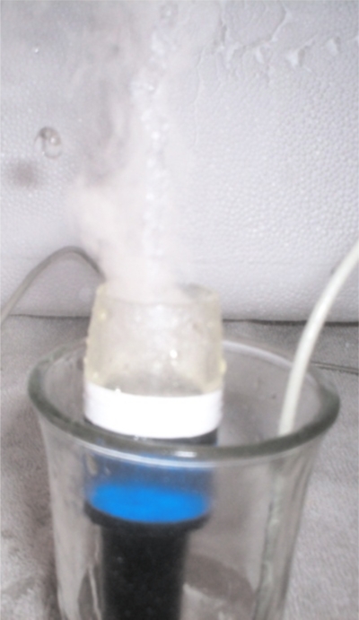
Adapting the circuitry for other ultrasonic transducers was straightforward. The function generator that replaced the crystal oscillator drove 1.7, 2.2, and 7.5 MHz PZT-4 focused transducers at powers that produced cavitation and levitation when submerged in degassed water as shown if Fig. 7. With the 7.5 MHz transducer, the MOSFETs began to heat to damage after 2 min at continuous full power. This was not surprising in view of the probe’s low electrical impedance (4 Ω), a current draw of 7.5 A, and greater MOSFET switching losses at the higher frequency. Thus, operating the 7.5 MHz probe continuously would require additional MOSFETs in parallel or the use of heat sinks to dissipate thermal energy.
Figure 7.
1.54 MHz ultrasound transducer levitating and cavitating water at full system power.
CONCLUSIONS
The portable therapeutic ultrasound system drives an ultrasound transducer with a very low output impedance ac source, so that power from the supply is efficiently transferred to the device. The device can operate in the range from 1 to 10 MHz, which spans the relevant range for medical therapeutic ultrasound and HIFU systems.
The ultrasound driving circuit has an output impedance of 0.3 Ω and provides switching of ±28.8 V. The device can provide more than 50 W of acoustic energy from the 1.54 MHz transducer using no impedance tuning. Because the device consists of multiple battery packs, voltage regulators were wired to the nearest battery level to reduce energy waste. Combining the LED on-light, the heating of MOSFETs, voltage regulators and resistors, along with a back calculation of the acoustic output energy measured, we calculated an energy waste of less than 10% from thermal heating. The device is much smaller and lighter than commercially available systems and costs only $150.00, of which 80% was battery costs.
ACKNOWLEDGMENTS
The authors would like to thank colleagues and reviewers for comments and feedback on this manuscript. We would also like to thank EBL Products, Inc. for supplying the piezomaterial and Transducer Engineering, Inc. for ultrasound probe design support. This research was funded in part by the National Science Foundation Graduate Fellowship Program, National Institutes of Health Grant No. NS-045236, and the Cornell University Presidential Life Science Fellowship.
APPENDIX: MATERIAL AND PARTS FOR INSTRUMENT
Parts list for amplifier components
-
(1)
Low output impedance MOSFET, quantity 8 (No. IRF7350, International Rectifier, Inc. or No. FDS4559, Fairchild Semiconductor, Inc.).
-
(2)
Pin driver, quantity 3 (No. EL7158ISZ, Intersil, Inc.).
-
(3)
1.54 MHz TTL crystal oscillator, quantity 1 (No. SE1216-ND, Epson Toyocom, Inc.).
-
(4)
10 kΩ, ±5%, resistor, quantity 3 (general).
-
(5)
820 Ω, ±5%, resistor, quantity 16 (general).
-
(6)
2.2 Ω, ±5%, resistor, quantity 8 (general).
-
(7)
1 Ω, ±5%, 5 W resistor, quantity 8 (general).
-
(8)
47 μF, ±20%, 50 V electrolytic capacitor, quantity 12 (general).
-
(9)
0.1 μF, ±20%, 50 V electrolytic capacitor, quantity 12 (general).
Parts list for housing and miscellaneous parts
-
(1)
Plastic enclosure, quantity 1 (No. 073, Serpac, Inc.).
-
(2)
Rotary switch, quantity 2 (No. 275–1386, Radio Shack, Inc.).
-
(3)
SPST 3-way switch, quantity 1 (No. 275–612, Radio Shack, Inc.).
-
(4)
LED, quantity 1 (No. 276–316, Radio Shack, Inc.).
-
(5)
Voltage regulator 5 V, quantity 1 (No. 276–1770, Radio Shack, Inc.).
-
(6)
Voltage regulator 12 V, quantity 2 (No. 276–1771, Radio Shack, Inc.).
-
(7)
Prototyping board, quantity 1 (No. 276–150, Radio Shack, Inc.).
-
(8)
dc power connector, quantity 1 (No. 274–1563, Radio Shack, Inc.).
-
(9)
NiCad 9.6 V battery with charger, quantity 6 (No. 23–432, Radio Shack, Inc.).
References
- Wu J. and Nyborg W., Emerging Therapeutic Ultrasound (2006). [Google Scholar]
- Aus G., Eur. Urol. 10.1016/j.eururo.2006.07.011 50, 927 (2006). [DOI] [PubMed] [Google Scholar]
- Mitragotri S., Nat. Rev. Drug Discovery 10.1038/nrd1662 4, 255 (2005). [DOI] [PubMed] [Google Scholar]
- Bailey M. R., Khokhlova V. A., Sapozhnikov O. A., Kargl S. G., and Crum L. A., Acoust. Phys. 10.1134/1.1591291 49, 369 (2003). [DOI] [Google Scholar]
- Harr G. and Coussios C., Int. J. Hyperthermia 10.1080/02656730601186138 23, 89 (2007). [DOI] [PubMed] [Google Scholar]
- Vykhodtseva N. I., Hynynen K., and Damianou C., Ultrasound Med. Biol. 10.1016/0301-5629(95)00038-S 21, 969 (1995). [DOI] [PubMed] [Google Scholar]
- Cesario D., Fujimura O., Mahajan A., Boyle N. G., and Shivkumar K., Contemporary Cardiology, Atrial Fibrillation from Bench to Bedside (2008), pp. 209–221. [Google Scholar]
- Park E. J., Jung K. I., and Yoon S. W., J. Acoust. Soc. Am. 107, 2788 (2000). [Google Scholar]
- G. K.Lewis, Jr., Olbricht W., and Lewis G. K., Proc. Meet. Acoust. 2, 1 (2008).19305636 [Google Scholar]
- G. K.Lewis, Jr., Wang P., Lewis G. K., and Olbricht W., Proceedings of the International Symposium on Therapeutic Ultrasound (AIP, New Yok, 2008).
- Newman C. M. H. and Bettinger T., Gene Ther. 10.1038/sj.gt.3302925 14, 465 (2007). [DOI] [PubMed] [Google Scholar]
- Lizzi F. L., Driller D. J., Silverman R. H., Lucas B., and Rosado A., Proc.-IEEE Ultrason. Symp. 1986, 981. [Google Scholar]
- Vaezy S., Shi X., Martin R. W., Chi E., Nelson P. I., Bailey M. R., and Crum L. A., Ultrasound Med. Biol. 10.1016/S0301-5629(00)00279-9 27, 33 (2001). [DOI] [PubMed] [Google Scholar]
- Crum L. A., Project Report, NASA2007.
- Owen N. R., Bailey M. R., Mortimer B. J. P., Kolve H., Hossack J., and Crum L. A., Proceedings of the 3rd International Symposium on Therapeutic Ultrasound, 2003, Vol. 26, pp. 399–404.
- Wood R. W. and Loomis A., Philos. Mag. 4, 417 (1927). [Google Scholar]
- Lynn J. G., Zwemer R. L., Chick A. J., and Miller A. E., J. Gen. Physiol. 10.1085/jgp.26.2.179 26, 179 (1942). [DOI] [PMC free article] [PubMed] [Google Scholar]
- Fry F. J., Sanghvi N. T., Morris R. F., Smithson S., Atkinson L., Dines K., Franklin T., and Hastings J., Proc.-IEEE Ultrason. Symp. 1986, 1001. [Google Scholar]
- Lee R. J., Buchanan M., Kleine L. J., and Hynynen K., IEEE Trans. Biomed. Eng. 10.1109/10.771202 46, 880 (1999). [DOI] [PubMed] [Google Scholar]
- G. K.Lewis, Jr., G. K.Lewis, Sr., and Olbricht W., Meas. Sci. Technol. 10.1088/0957-0233/19/10/105102 19, 105102 (2008). [DOI] [PMC free article] [PubMed] [Google Scholar]
- Maruvada S., Harris G. R., and Herman B. A., J. Acoust. Soc. Am. 10.1121/1.2431332 121, 1434 (2007). [DOI] [PubMed] [Google Scholar]
- Redwood M. and Lamb J., Proc. IEEE 103, 773 (1956). [Google Scholar]


