
Figure 1.
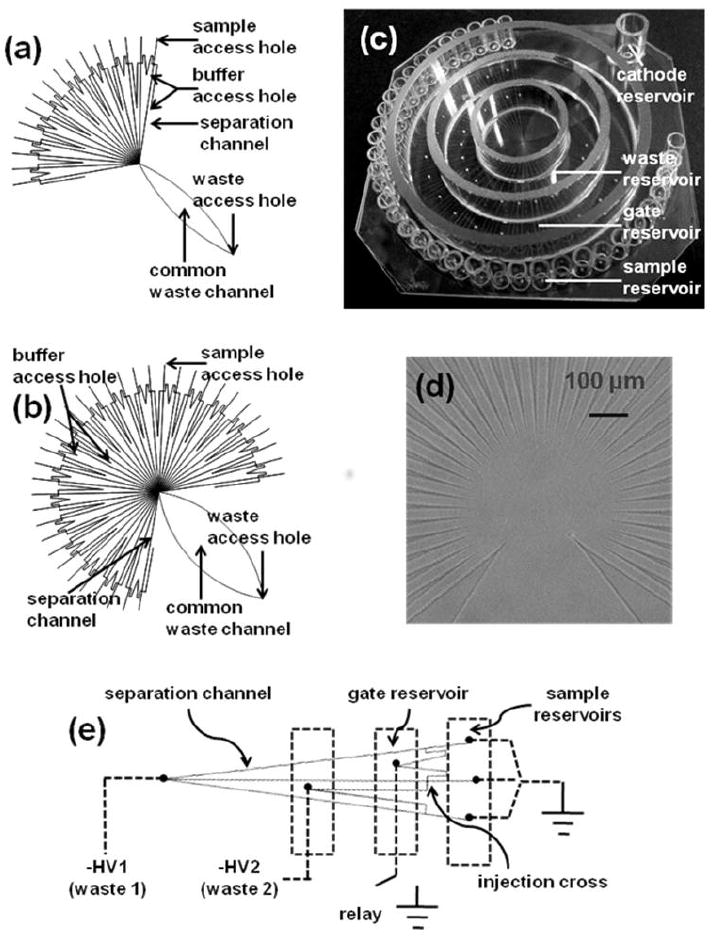
Microfluidic devices used for parallel electrophoretic enzyme assays. (a). Design of microfluidic network containing 16 parallel separation channels. Dimensions of each section were as follows: 7 mm from sample access hole to injection cross; 27 mm for separation channel (from injection cross to center where all separation channels converge); 8 and 13 mm for two other channels connecting the injection cross; 35 mm long and 6 mm wide at the widest point for the common waste channel. (b) Design of 36-channel network. Dimensions were similar to the 16-channel chip except the common waste channel was 40 mm long and 13 mm wide at the widest point. (c) Photograph of finished 36-channel chip. 1 cm long glass tubes of volume of 50 μL each were used for individual sample reservoirs. Two groups of access holes were separately connected to gate reservoir and waste reservoir which were formed by using three glass rings. Common waste channel led to another cathode reservoir to which −HV was applied. (d). Bright-field image of the detection area on the 36-channel chip. (e) Repetitive units of microfluidic network. Electrokinetic injection procedure is described in experimental section.