
Figure 3.

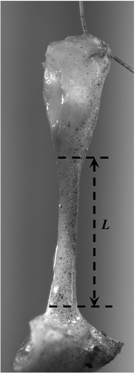
(a) A schematic representation of two load cycles. The stretch of the tissue specimen is denoted by (—) and applied displacement is represented by (- - - -). Between the points P1 and P2 the sutures attached to both ends of the tissue specimen are slack and no compressive load can be applied; (b) a photograph of a vocal fold ligament specimen mounted in the lever system with suture attachment through dissected sections of the thyroid cartilage (bottom) and the arytenoid cartilage (top). The initial length (mounting length) of the specimen (L) is shown.