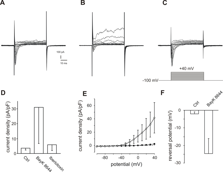
Figure 5.
Activation of BK channels in ARPE-19 cells by the BayK 8644-induced activation of L-type Ca2+ channels. A: Control currents were evoked by 15 depolarizing voltage steps of 50 ms duration with 10 mV increment before application of BayK 8644 (holding potential −100 mV). B: The same cell after application of 5 μM BayK 8644 displayed a considerable increase of outward currents. C: The BayK 8644-induced outward currents are blocked by the additional application of 100 nM iberiotoxin. Note that in this cell a transient inward current activated by depolarisation of the cell can be seen. This becomes smaller in the presence of BayK8644 (B) because the current is counterbalanced by the outward current which became larger. However, when the outward current was blocked by additional application of iberiotoxin (C) then the inward current shows in the presence of BayK 8644 an amplitude which is larger (130% of control) than that before application of BayK 8644 (A). Thus, this inward current is most likely a current through L-type Ca2+ channels. Since comparable strong L-type currents were only rarely observed, this effect of the BayK8644/iberiotoxin application was not further studied. D: Mean current densities measured at +40 mV are considerably increased by the application of BayK 8644. Abbreviations: Control current (Ctrl); current densities after application of 5 μM BayK 8644 (BayK 8644); current densities after additional application of 100 nM iberiotoxin (iberiotoxin; n=3). E: The comparison of current-voltage relationship of current densities before (filled circles) and after (open circles) application of 5 μM BayK 8644 illustrates the voltage-dependent current increases induced by BAYK 8644 application (n=5). For illustration the zero current is indicated by a dashed line. F: BayK 8644 application shifted the reversal potential to negative potentials. The reversal potential was defined as the point of intersection of the I/U-lines with the x-axes. I/U-lines were generated by plotting the maximal currents evoked by the depolarizing steps in the pulse protocol described in A against the potentials (n=5).

