
Fig. 1. Structural configuration of the multi-modular, tensegrity, stress fiber model.
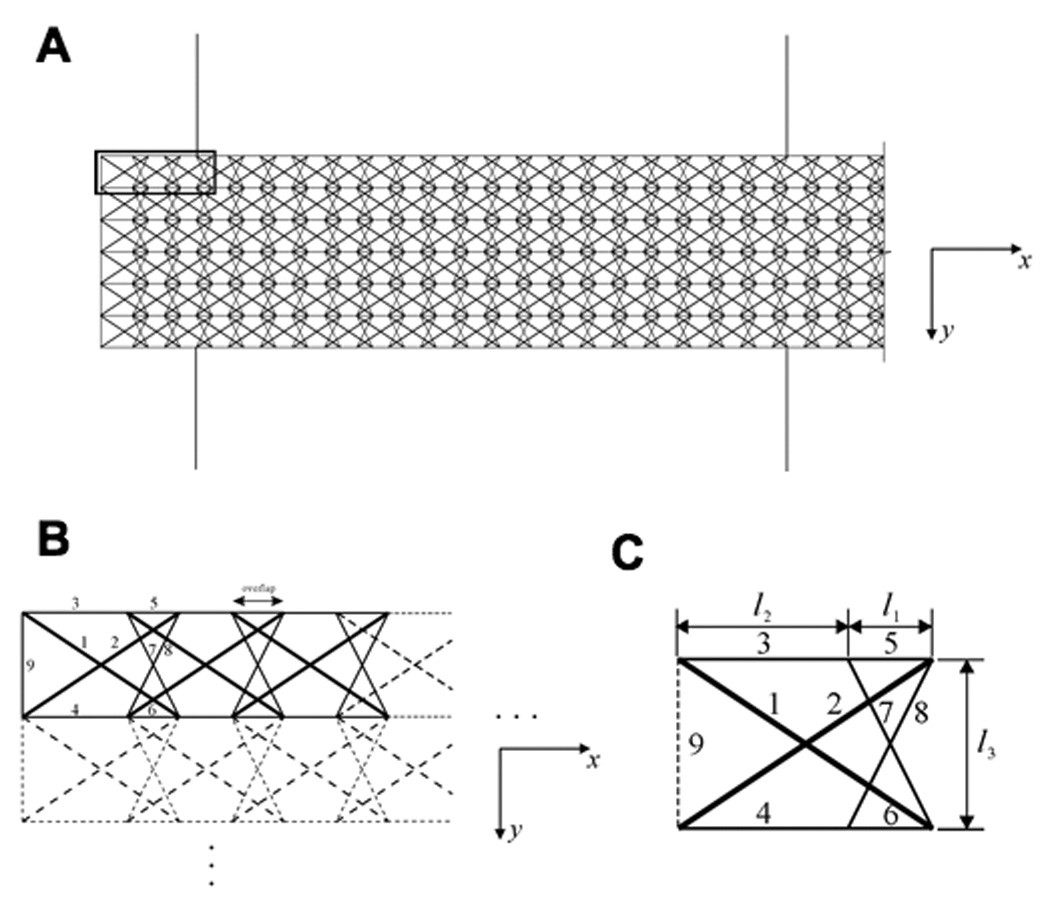
A) Organization of a large section of the planar multi-modular tensegrity; the bold rectangle at the upper left indicates the area which is shown in greater detail in B. B) Assembly of individual modules into a self-equilibrium tensegrity structure. C) A single tensegrity module from A and B, with elements labeled: elements 1 and 2 (bold lines) are struts; 3–8 are cables (thin lines), and 9 (dashed line) is an additional cable for end modules. The modules connect one by one in the x-direction by overlapping by a distance of l1, and they can be replicated in the y-direction by shifting a distance of l2. Element 9 is only added to the distal ends of the modules of the model to mimic fixed ends of the SF and thereby, maintain structural self-equilibrium .