
Fig. 3. Response of a stress fiber to puncturing.
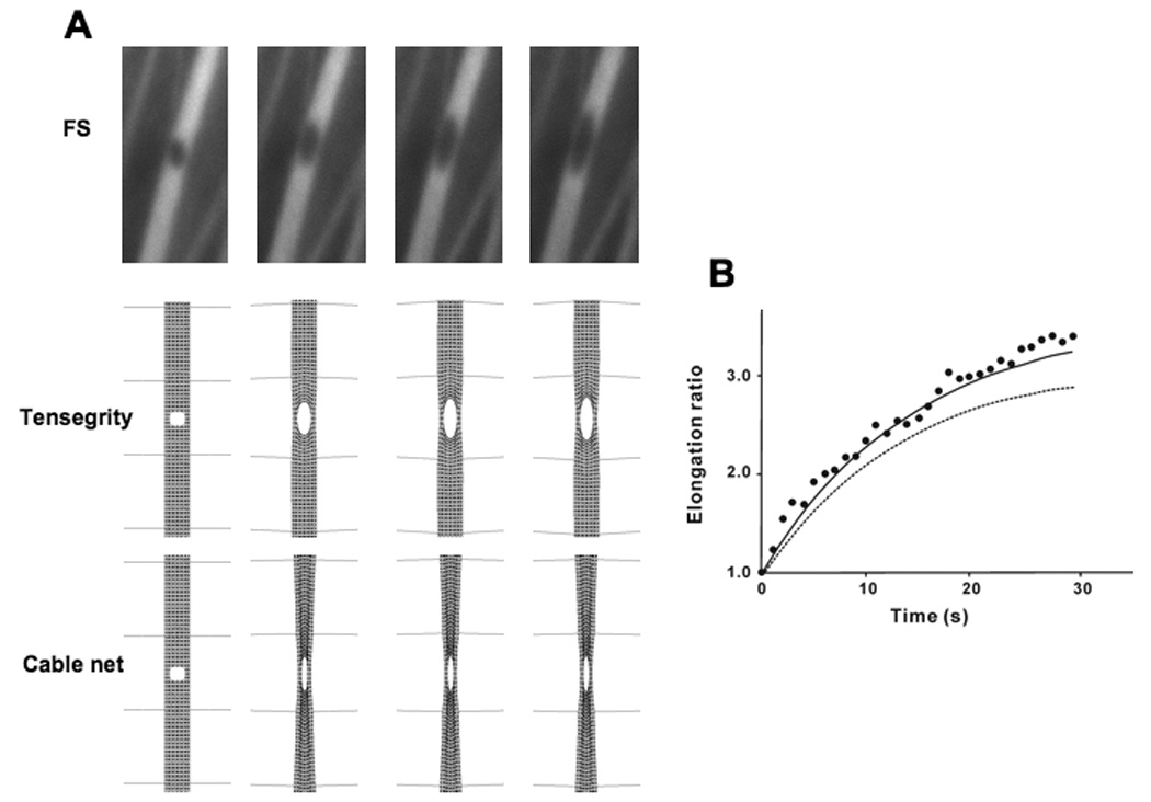
A) Progressive elongation of a puncture hole (300 nm diameter) produced in a YFP-labeled SF with a femtosecond laser (Kumar, 2006) over a period of 15 sec (left views), and similar responses depicted in a simulation of the tensegrity SF model (right views). B) Graphic depiction of the time course of hole elongation along the main axis of the SF showing that the results of the tensegrity simulation (black line) fit well with previously reported experimental results (black circles; 5). The elongation ratio is defined as the ratio of increased diameter along the main axis to the initial diameter. C) A tensegrity SF model that also incorporates lateral guy wire cables to model lateral filamentous constraints observed in past electron microscopic studies effectively predicts the lateral thickening of the SF puncture wound, as observed in the past experimental studies.