
Fig. 6.
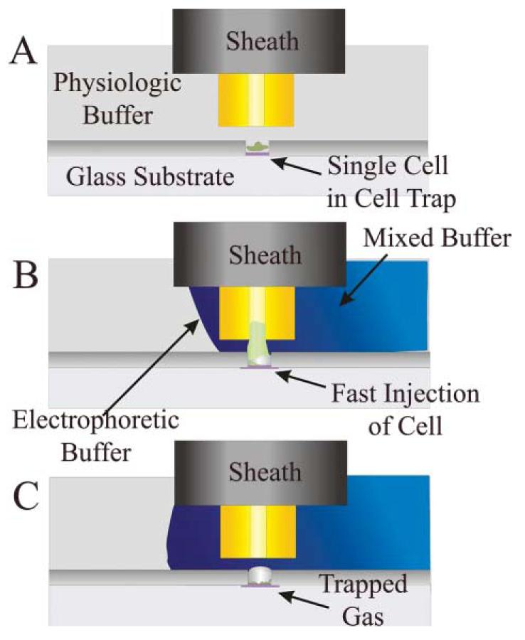
Cell traps coupled with a capillary electrophoresis system. (A) Shown is a schematic of the side view of a capillary electrophoresis system over a cell cultured in a cell trap before lysis of the cell. (B) Shown is the same system in (A) but at the moment of when the electric field is applied to lysis the cell in the cell trap. Simultaneous with cell lysis, the electrophoretic buffer flow is initiated so that the capillary tip and cell are surrounded by electrophoretic buffer. A voltage is also applied across the capillary initiating electroosmotic fluid flow into the capillary. The buffer flows toward an outlet placed in the cell chamber to the right of the capillary. (C) A schematic of the residual bubble in the cell trap is shown following cell lysis. The contents of the cell have moved into the capillary. Please see ref. 11 for a fuller description of capillary electrophoresis using a sheath-flow system to supply electrophoretic buffer.