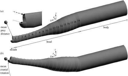
Figure 2.
Outline of the geometry of the CFD model at the (a) start and (b) end of head rotation. The head includes 19 elliptical cylinders with cross sections equal to the model shown in figure 1. The upper jaw edge is rounded (dashed arrow) and the lower jaws are modelled as a hollow quarter spheroid (dotted arrow). The body is modelled as an elliptical cylinder translating ventroanteriorly to follow the rotation of the head.

