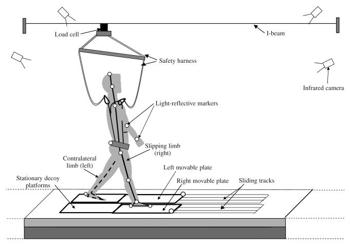
FIGURE 1.
Schematic diagram of the experimental setup with approximate position of the participant at touchdown of the training (right limb). Unfilled circles indicate positions of passive–reflective markers on the body segments and movable platform. Solid and dotted lines joining the markers represent the body-segment links used to calculate the whole-body center of mass. The I-beam and safety harness system were much higher than shown (9 m above the ground). The I-beam extended the length of the 7-m walkway. The two sliding devices were placed side by side to enable inducing the bilateral slips. The low-friction, nonmotorized movable top plates were mounted on a frame with linear bearings. Once released, the movable platforms were free to slide along the track on the linear bearings. These devices were locked and embedded in a 7-m walkway and made less apparent by the stationary decoy platforms.

