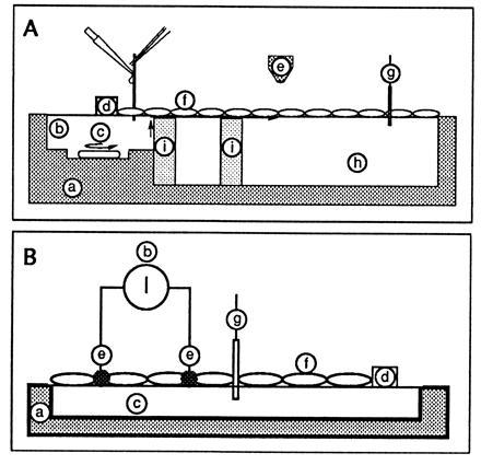
Figure 1.

Schematic drawing of the monolayer trough. (A) Fluorescence detection. This was the setup described in ref. 5. Sites: a, Plexiglas trough (to reduce light scattering); b, injection of acid; c, stirrer to homogenize the injection compartment; d, Teflon barrier (to limit the film and to define the part in contact with the acidic subphase); e, fluorescence observation area (detection was either with a PM tube or with an intensified video camera); f, monolayer (the protein film was obtained by pouring a small volume of a protein solution along a glass rod implanted across the water/air interface); g, surface pressure transducer; h, aqueous subphase; i, glass barrier to prevent proton diffusion in the bulk. The fluorescence baseline was obtained without spreading film. The 100% fluorescence was given after spreading the protein film on a 1 M NaCl/1 mM Mops buffer (pH 7.4). Acid was then injected in b (bringing the local bulk pH to 2). The transfer of protons to site h was detected by the associated decrease in fluorescence emission. (B) Conductance detection. The procedure and setup are described in the text.
