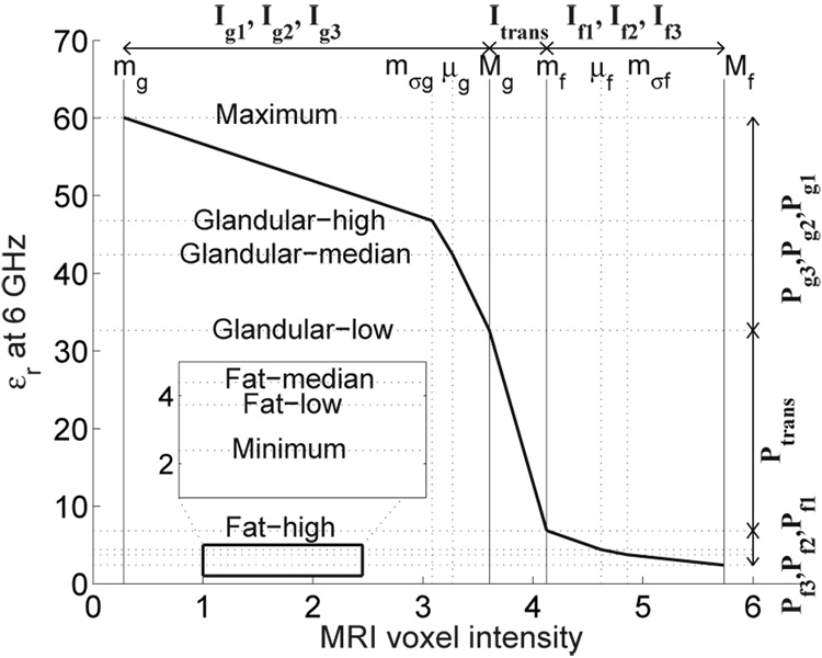
Fig. 4.
A representative piecewise-linear map illustrating the linear mapping between seven intervals along the MRI voxel intensity axis (Ig1, Ig2, Itrans, If1, If2, If3) and seven intervals along the dielectric properties axis (Pg1, Pg2, Ptrans, Pf1, Pf2, Pf3). The MRI in this example is of a patient with extremely dense breast tissue.

