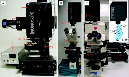
FIG. 1.
MOSI system, showing the arrangement of the components during (A) mesoscopic and (B and C) microscopic measurements. 1, HS camera; 2, motorized linear stage; 3, LEDs with collimating optics and short-pass excitation filters; 4, LED power supply; 5, holder for the long-pass emission filter; 6, substrate for the sample; 7, microscope; 8, motor for microscope table movement. (Inset) Orientation and angular divergence (not to scale) of the LOV imaged by the camera.

