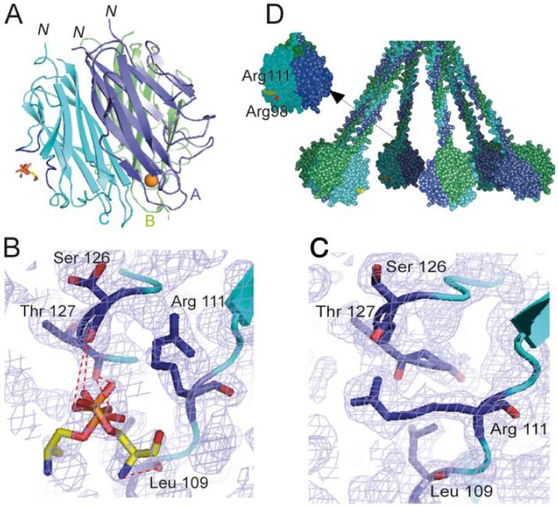
FIGURE 6.
X-ray structure of a phosphoserine-C1q GR complex. A, Overall view of the interaction. Subunits A-C are colored blue, green, and cyan, respectively, and are shown in ribbon representation. The ligand is shown in stick representation. The Ca2+ ion bound to the GR is represented as a golden sphere. In subunit C, the two surface loops involved in ligand stabilization are colored dark blue. N indicates the N-terminal end of the subunits, connecting the GR to the preceding collagen-like triple helix. According to the current C1q model (17), the B subunit marks the external face of each GR in the whole C1q molecule and the target surface is expected to lie roughly at the bottom of the GR structure. B, Detailed view of the interactions between subunit C and phosphoserine. The two alternative conformations of phosphoserine are shown. Electron densities (2mFo-Fc) are contoured at the 1σ level. C, Comparative detailed view of the phosphoserine-binding region in the native GR structure, illustrating the extended conformation of the side chain of Arg111. D, Overall model of the C1q molecule (17) illustrating the positioning of the phosphoserine-binding site. Arg111 and Arg98 are colored yellow and red, respectively. This figure was designed using Pymol and Grasp (62).

