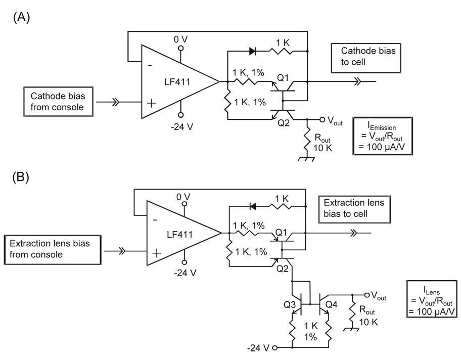
Figure 1.
(A) Analog circuit designed to measure the emission current of the EDD cathode. Q1 and Q2 are a matched pair of npn transistors. (B) Analog circuit designed to measure the extraction lens current. Q1/Q2 are a matched pair of pnp transistors, and Q3/Q4 are a matched pair of npn transistors. The electron current sourced by the cathode and sunk by the lens are mirrored and converted to a voltage by 10K resistors.

