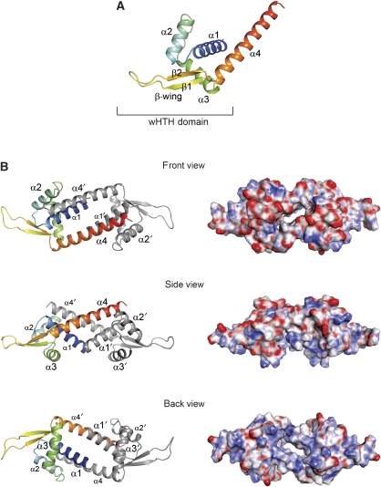
Figure 1.
Overall structure of apo–LmrR. (A) Ribbon representation of a single LmrR subunit with a rainbow colour gradient from the N terminus (blue) to the C terminus (red). Secondary structure elements are indicated with labels. (B) The apo–LmrR dimer is shown in three orientations, related by 90° rotations, resulting in a front view (along the two-fold rotation axis facing the α4 helices), a side view (perpendicular to the two-fold axis) and a back view (along the two-fold axis facing the α1 and α3 helices). Helices are indicated with labels. The left panel shows the LmrR dimer in ribbon presentations, the right panel in electrostatic surface representations. The red and blue in the surface representations indicate the strength of the electrostatic surface potential (red, negative charge; blue, positive charge).

