
Fig. 5.
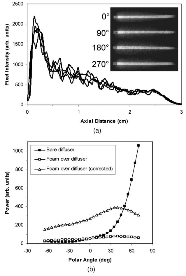
(a) Axial emission profiles and images of a single 1-mm-diam diffuser acquired at azimuth angles of 0, 90, 180, and 270 deg to illustrate the circumferential uniformity and (b) polar emission profile at an axial distance of 0.5 cm of a 1-mm-diam bare diffuser and the same diffuser surrounded by a 1.5-mm-thick SMP foam collar. In (b), a “corrected” foam-covered diffuser curve is included to better illustrate the redistribution of the emitted light. The curve was obtained by increasing the measured power values by a factor of 5 to approximately compensate for the reduced irradiance at the surface imaged by the goniometer due to the 4× increase in diameter and ∼20% loss due to absorption by the foam (measured using the integrating sphere). In (a) and (b), the diffuser was made using a nozzle translation speed of 3 mm/s, a blasting pressure of 50 psi, and a nozzle-to-sample distance of 3 cm.