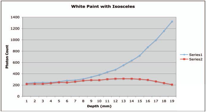
Figure 12.
Plot of detector A (series 1) and detector B (series 2) as a function of depth of a point source of light from the detector. The basic geometry is shown in Figure 8. The shared reflector is an isosceles right triangle (metallic reflector), the unshared crystal sides have a white reflector, and the end cap opposite the detector is a white reflector.

