
Figure 8.
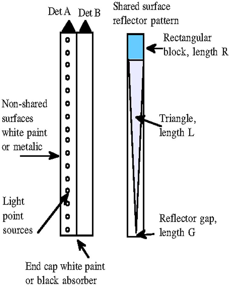
Basic geometry of simulations. Light was generated from a single point that was moved along the long axis of the crystal mounted to detector A. The shared surface between the crystals included a reflector that could consist of 3 parts (a rectangle of length R, an isosceles or right triangle of length L that stopped short of the end of the crystal leaving a “gap” of length G.