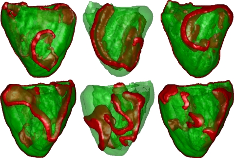
Fig. 3.
Mother rotor VF. Wavefronts are shown in red. Top: LV view; bottom: RV view. Left: location of the initial spiral; middle: after 3.5 s; right: after 10 s. Note the stable spiral in the LV free wall, whereas breaks occurred in the RV free wall. The spiral in the LV wall remained stable until the end of the simulation (up to 12 s simulated). Breaks in the RV were driven by the mother rotor spiral.

