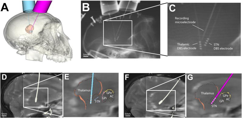
Figure 2.
Surgical planning and electrode implantation. A. Cicerone software was used to plan locations for chambers targeting thalamus (left hemisphere) and STN (right hemisphere). B. X-ray image taken during a recording session. C. Zoomed in view of figure B. In this example, the microelectrode was 2.5 mm posterior to the STN DBS electrode. D, F. the post-DBS-implantation CT was coregistered with pre-DBS-implantation MRI to define the DBS electrode location in the brain. The white structure is the contour of the electrode extracted from the post-DBS-implantation CT. E, G. Cicerone was used to visualize electrode location with respect to a brain atlas warped to match the neuroanatomy of the animal.

