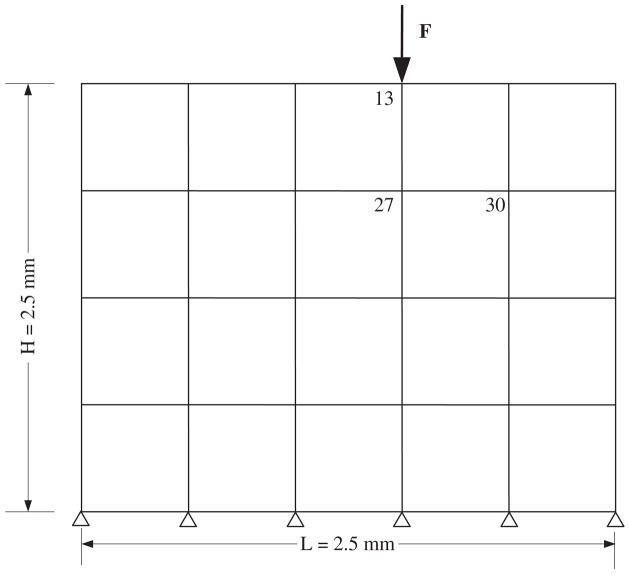
Fig. 1.
The cell–ECM numerical model with key node numbers noted. The model illustrates the macroscopic ‘tissue’ level in which chondrocytes are assumed to be embedded at node locations. An external force, F, was applied at node 13. Two displacement output measurement locations were identified at nodes 27 and 30. The mass and stiffness system matrices (Eq. (8)) produced from this finite element analyses were used as input for the inverse solution.

