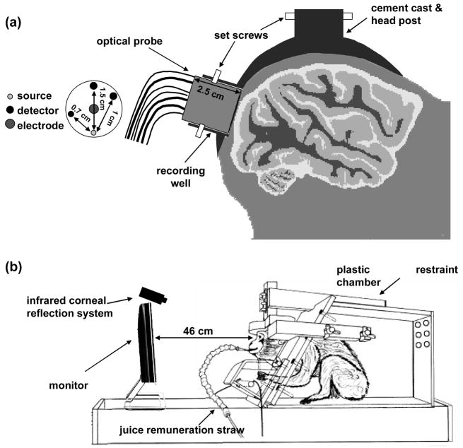
Figure 1.
Panel a shows a schematic of the optical probe inserted in the recording well, the cemented post on the animal head, and the probe geometry with indicated source detector distances. Panel b shows the experimental setup with the animal restrained in a custom-made chamber in front of a monitor.

