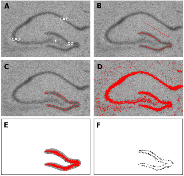
Figure 1.
Four methods of selecting the dentate gyrus. The first method used a segmented line drawn down the centre of the DG (B). The background was measured with another line midway between the CA1 and the suprapyramidal blade of the DG. The second method used the polygon tool to outline the DG by hand (C). The third method used a thresholding approach and included only those parts of the DG that were three standard deviations above the mean background GL (D-F). The threshold was adjusted based on the calculated value (D) and then the DG was outlined and the background cleared in order to isolate the DG (E). The outline was only approximate as there was no need to distinguish between background and foreground precisely. The average GL and area were then calculated and the outline of the selected region is shown (F). The fourth method used a mixture model to determine the optimal threshold, and the rest of the analysis was carried out as above. CA = Cornu Ammonis, DG = Dentate gyrus, Hi = Hilus.

