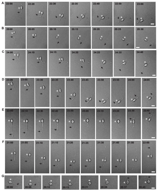
Fig. 3.
Four distinct modes of granule cell turning in vitro. (A)Sequential images of a granule cell represent the 1st mode of turning. The tip of the leading process turned to the left side and then, the cell body followed the changes. (B, C) Sequential images of granule cells represent the 2nd mode of turning. The tip of the leading process bifurcated, and both branches extended in the opposite direction. Subsequently, one of the branches collapsed and retracted, and the cell body followed the direction of extension of the remaining branch. (D) Sequential images of a granule cell represent the 1st and 3rd modes of turning. The tip of the leading process of the granule cell turned to the left side and then, the cell body followed the changes. Thereafter, the growth cone of the tip of the leading process collapsed. The trailing process then started to develop a new growth cone at the tip and converted into a new leading process. Sequentially, the soma started to migrate in the direction of the extension of the new leading process. (E and F)Sequential images of granule cells represent the 3rd mode of turning. The leading process of the granule cells transformed to the trailing process and the trailing process became the leading process. Thereafter, the cells started to migrate in the reversed direction. (G) Sequential images of a granule cell represent the 4th mode of turning. The granule cell completely withdrew the leading process, and extended a new leading process. Subsequently, the cell migrated toward the direction of the extension of the new leading process. Bar: 10 μm in A, D, E, F, 12 μm in B, and 8 μm in C, G. In A–G, asterisks and arrows indicate the granule cell somata and the leading processes, respectively. The numbers in each photograph represent the elapsed time after in vitro.

