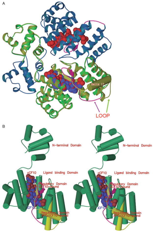
Fig. 5. Comparison of PrgX conformation when bound to cCF10 and iCF10.
A. Half of a PrgX tetramer is depicted. The blue and green ribbons show the structure of PrgX when complexed with cCF10. The CTD of cCF10-bound PrgX is shown in magenta: the arrows depict a small beta sheet formed from the same residues that comprise helix 17 (barrel) of the apo-protein (Shi et al., 2005); cCF10 is represented by the red balls. The yellow/green ribbon superimposed on the bright green PrgX monomer delineates the structure of iCF10-bound PrgX. iCF10 is represented by the bright blue balls superimposed on the red cCF10 structure. The structure of iCF10-bound PrgX is shown in yellow-green with helix 17 represented by a barrel: this complex retains the apo-PrgX conformation.
B. Comparison of monomers of PrgX when bound to cCF10 or iCF10 (stereo image). The yellow-green cylinders and ribbon indicate the structure of the C-terminus when iCF10 is bound. The magenta ribbon shows the structure of the C-terminus when cCF10 is bound.

