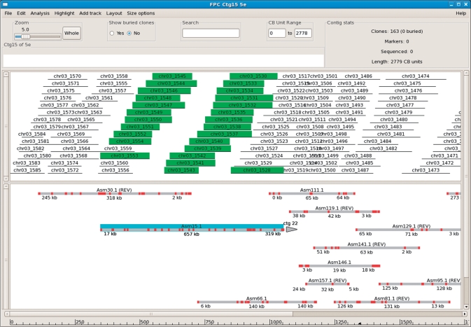
Figure 1.
DSI alignment within FPC. The top track shows the clones of FPC contig 15, while the bottom track shows the aligned draft sequence contigs. Draft contig Asm15.1 was clicked with the mouse causing it to highlight in blue, and the associated clones (those having BESs contained in Asm1.1) are also highlighted in the clone track. Alignments that have a reversed orientation are indicated by the notation ‘REV’, as seen on Asm30.1 at the left. The alignment of Asm15.1 illustrates detection of an assembly error, as described in the text.The draft contig lines are drawn to match the extent of the clones with which they share BES anchors; this makes small contigs appear larger than they actually are. Also, the alignment start/end labels reflect the locations of the first/last BES anchors, so they typically do not start exactly at 0 kb or end at the sequence endpoint.

