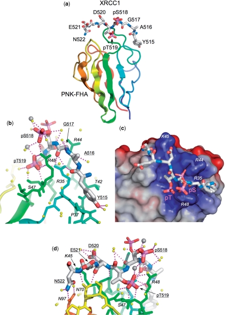
Figure 3.
Structure of PNK–FHA–XRCC1 phosphopeptide complex. (a) Overview of the binding of the XRCC1 peptide (stick model) to residues forming the inter-strand loops in the PNK–FHA domain (cartoon rainbow coloured N-terminal:blue → C-terminal:red). This and all other molecular graphics were made with MacPyMol (DeLano Scientific). (b) Interactions of the N-terminal end of the XRCC1 peptide with PNK–FHA (see text for details). The phosphate group on pSer518 shows dual conformations in the crystal structure, (shown as thick and thin sticks), due to interactions with a calcium ion involved in formation of the crystal lattice. Ordered water molecules are shown as yellow spheres, Ca2+ ions as larger grey spheres. (c) The central part of the XRCC1 peptide consisting of the negatively charged residues pSer518, pThr519 and Asp520 binds in a very basic recess on the FHA domain surface, generated by the side chains of arginine residues 35, 44 and 48, and Lys 45. The molecular surface of PNK–FHA is shown coloured by electrostatic potential – positive:blue → negative:red. (d) Interactions of the C-terminal end of the XRCC1 peptide (see text for details). The C-terminal Asn522 of the XRCC1 peptide is anchored by a bidentate amide-amide interaction with PNK residue Asn97.

